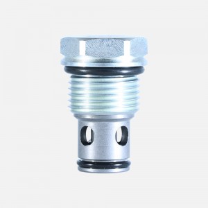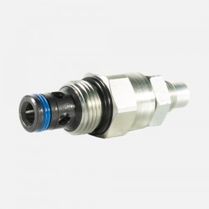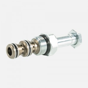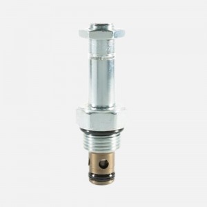
Two-way proportional relief valve 22BY-10
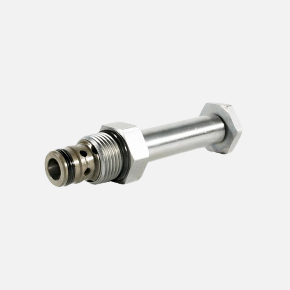


Product Features
1. 12 and 24 volt coils standard.
2. Industry common cavity.
3. Optional waterproof E-Coils rated up to IP69K.
Product Specifications
| Operating Pressure | 240 bar (3500 psi) |
| Maximum Control Current | 1.10 A for 12 VDC coil; 0.55 A for 24 VDC coil |
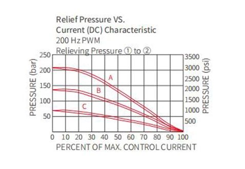
| Relief Pressure Range from Zero to Maximum Control Current | A: 207 to 10.3 bar (3000 to 150 psi);
B: 138 to 10.3 bar (2000 to 150 psi); C: 69 to 10.3 bar (1000 to 150 psi) |
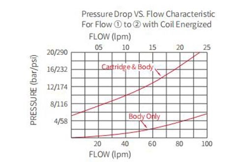
| Rated Flow | 75.7 Ipm (20 gpm),DP=14.8 bar (215 psi), Cartridge only, ① to ② coil energized |
| Maximum Pilot pressure | 0.76 lpm (0.2 gpm) |
| Hysteresis | Less than 3% |
| Temperature |
-40 to 120℃ |
| Fluids | Mineral-based or synthetics with lubricating properties at viscosities of 7.4 to 420 cSt (50 to 2000 sus) |
| Installation Recommendation | When possible, the valve should be mounted below the reservoir oil level. This will maintain oil in the armature preventing trapped air instability. If this is not feasible, mount the valve horizontally for best results. |
| Cartridge | Weight: 0.18 kg. (0.4 lbs.); Steel with hardened work surfaces. Zinc-plated exposed surfaces;
Seal:O-rings and back-up rings. Polyurethane seals recommended for pressures over 240 bar (3500 psi). |
| Standard Ported Body | Weight: 0.16 kg. (0.35 lbs.); Anodized high-strength 6061 T6 aluminum alloy, rated to 240 bar (3500 psi); Ductile iron and steel bodies available |
| Standard Coil | Weight: 0.27 kg. (0.60 lbs.); Unitized thermoplastic encapsulated, Class H high temperature magnetwire. |
| E-Coil | Weight: 0.41 kg. (0.90 lbs.); Perfect wound, fully encapsulated with rugged external metal shell; Rated up to IP69K with integral connectors. |
Product Operation Symbol
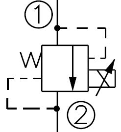
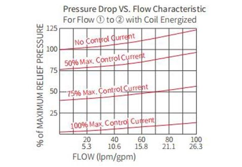
The Two-way proportional relief valve 22BY-10 blocks flow from① to ② until sufficient pressure is present at ① to open the valve by overcoming the preset-induced spring force. With no current applied, the valve will relieve at±50 psi of the range maximum. Applying current to the coil decreases the induced spring force, thereby reducing the valve setting.
Note:This valve is ideal for hydraulic fan drive applications.
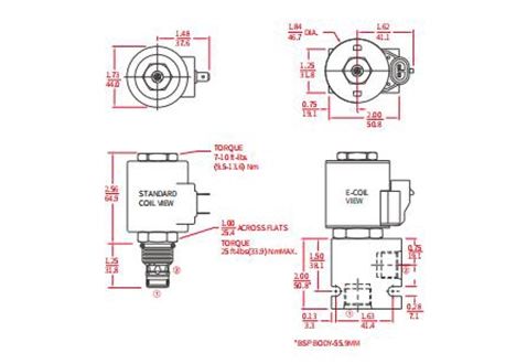
Performance/Dimension
WHY CHOOSE US
How we work
Development (tell us your machine model or design)
Quotation (we will provide you with a quotation as soon as possible)
Samples (samples will be sent to you for quality inspection)
Order (placed after confirming quantity and delivery time, etc.)
Design (for your product)
Production (producing goods according to customer requirements)
QC (Our QC team will inspect the products and provide QC reports)
Loading (loading ready-made inventory into customer containers)

Our Certificate

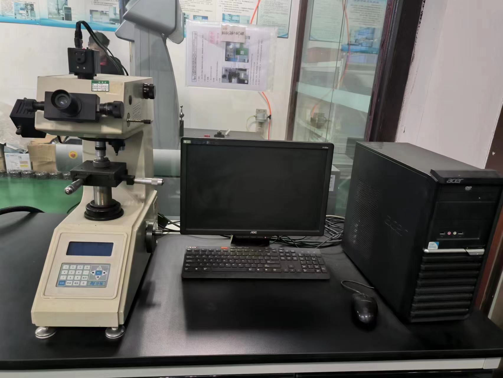
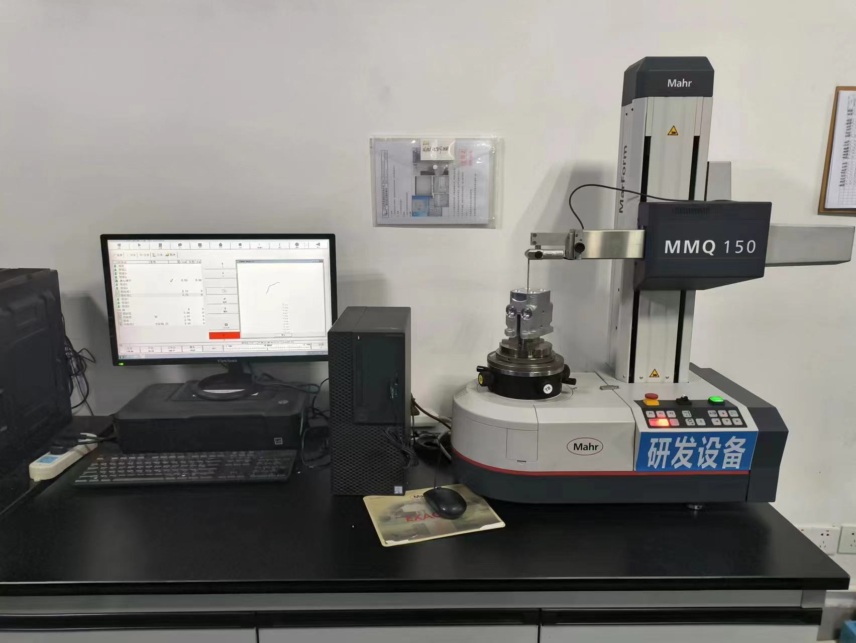
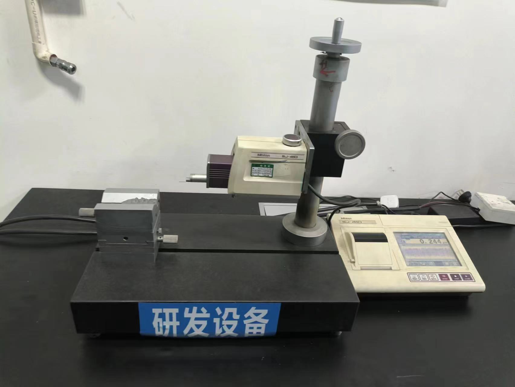
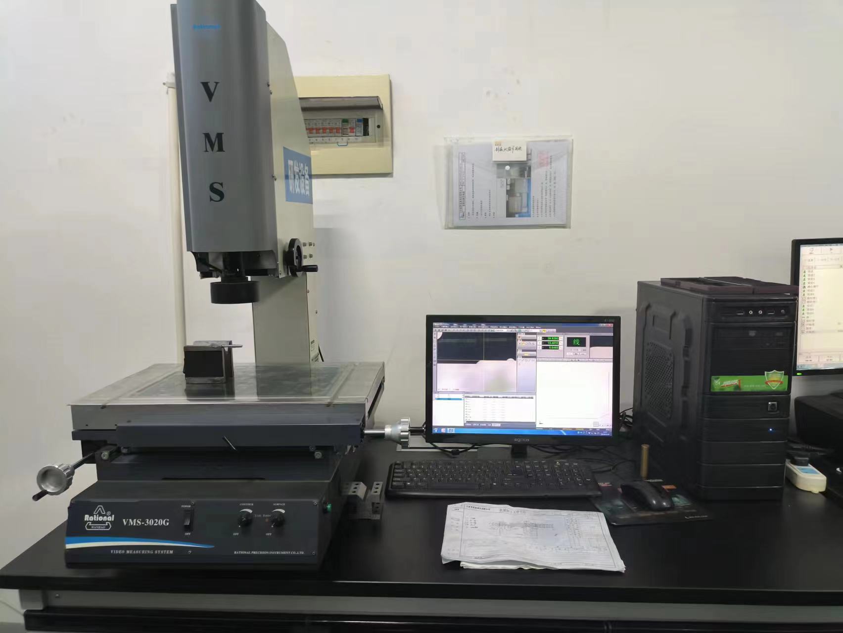
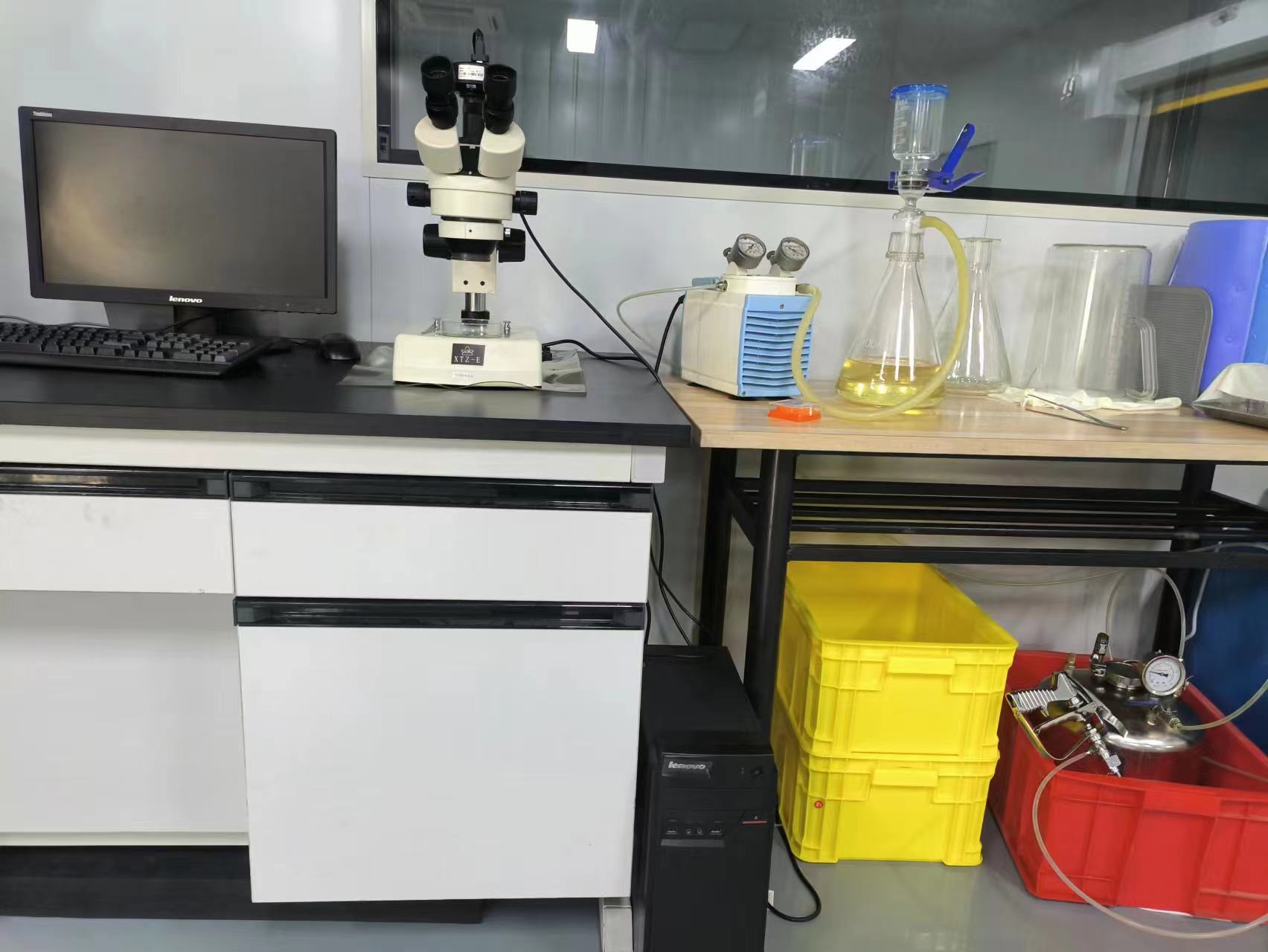
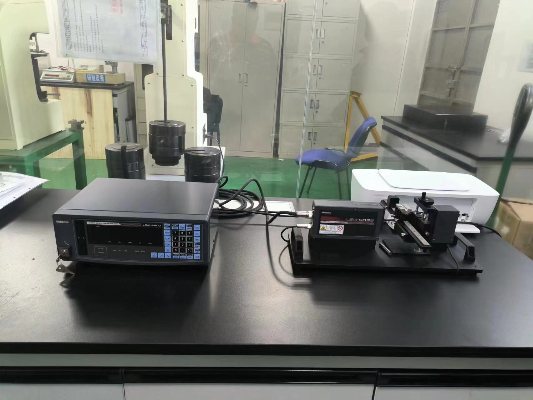
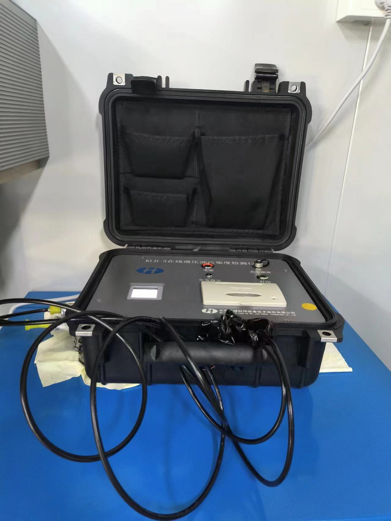
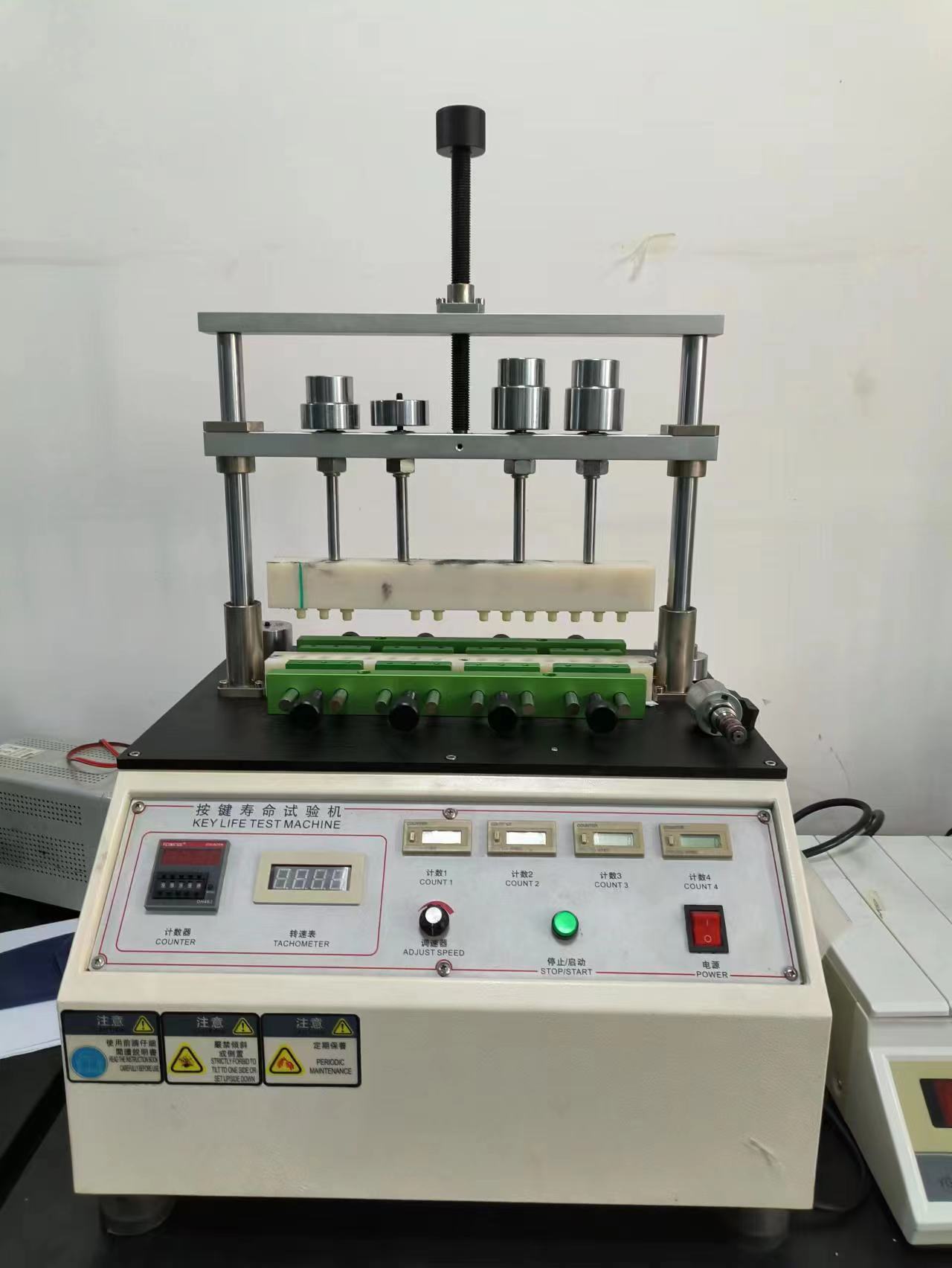
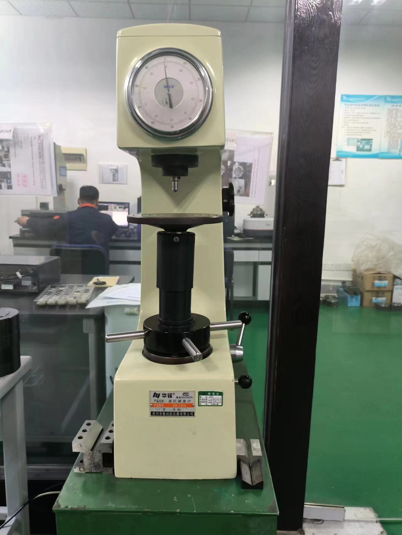
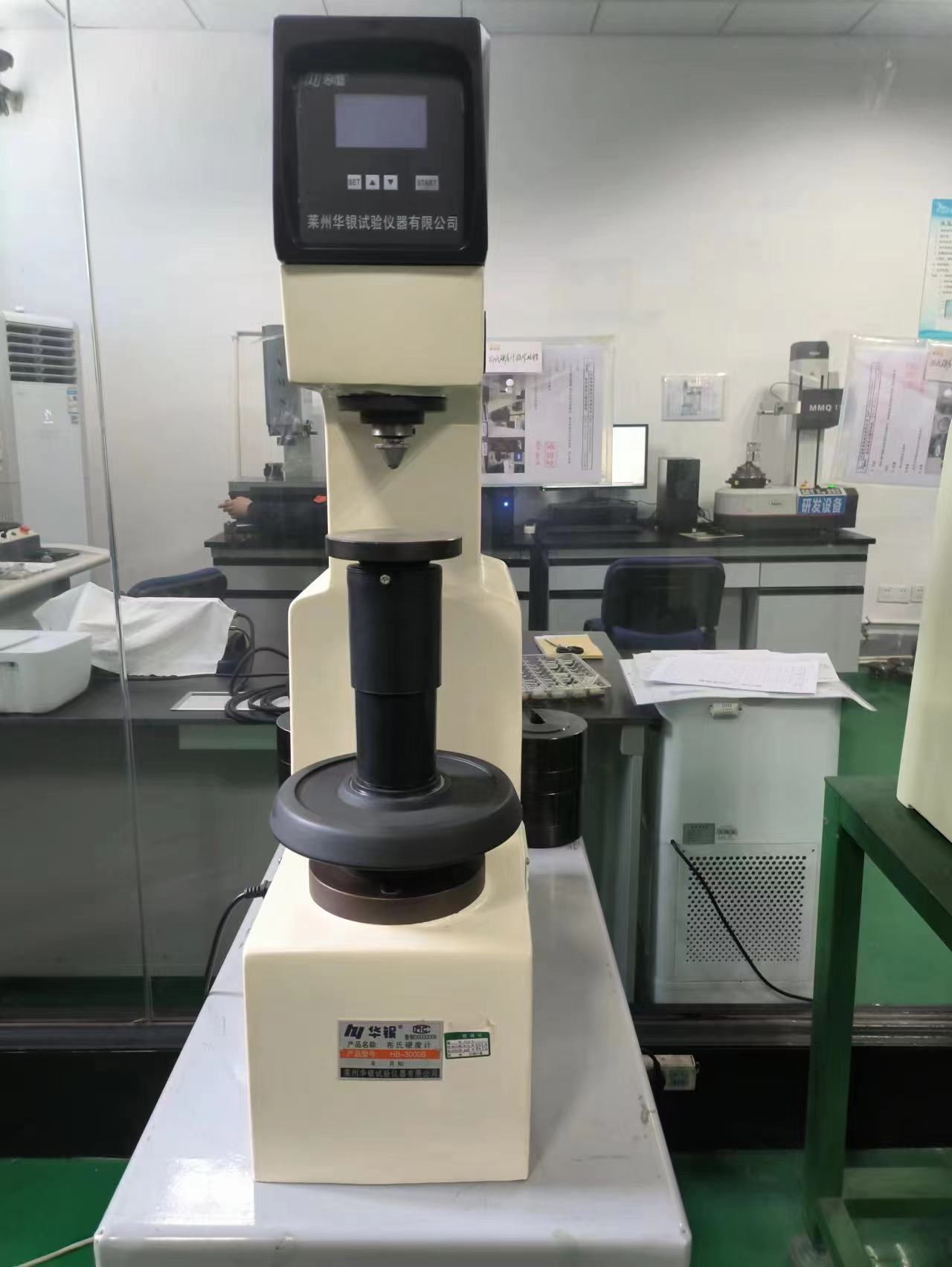
Quality Control
To ensure the quality of factory products,we introduce advanced cleaning and component testing instruments, 100% of the assembled products pass factory testing and the test data of each product is saved on a computer server.
R&D team
Our R&D team consists of 10-20 people, most of whom have about 10 years of work experience.
Our R&D center has a sound R&D process,including customer survey, competitor research, and market development management system.
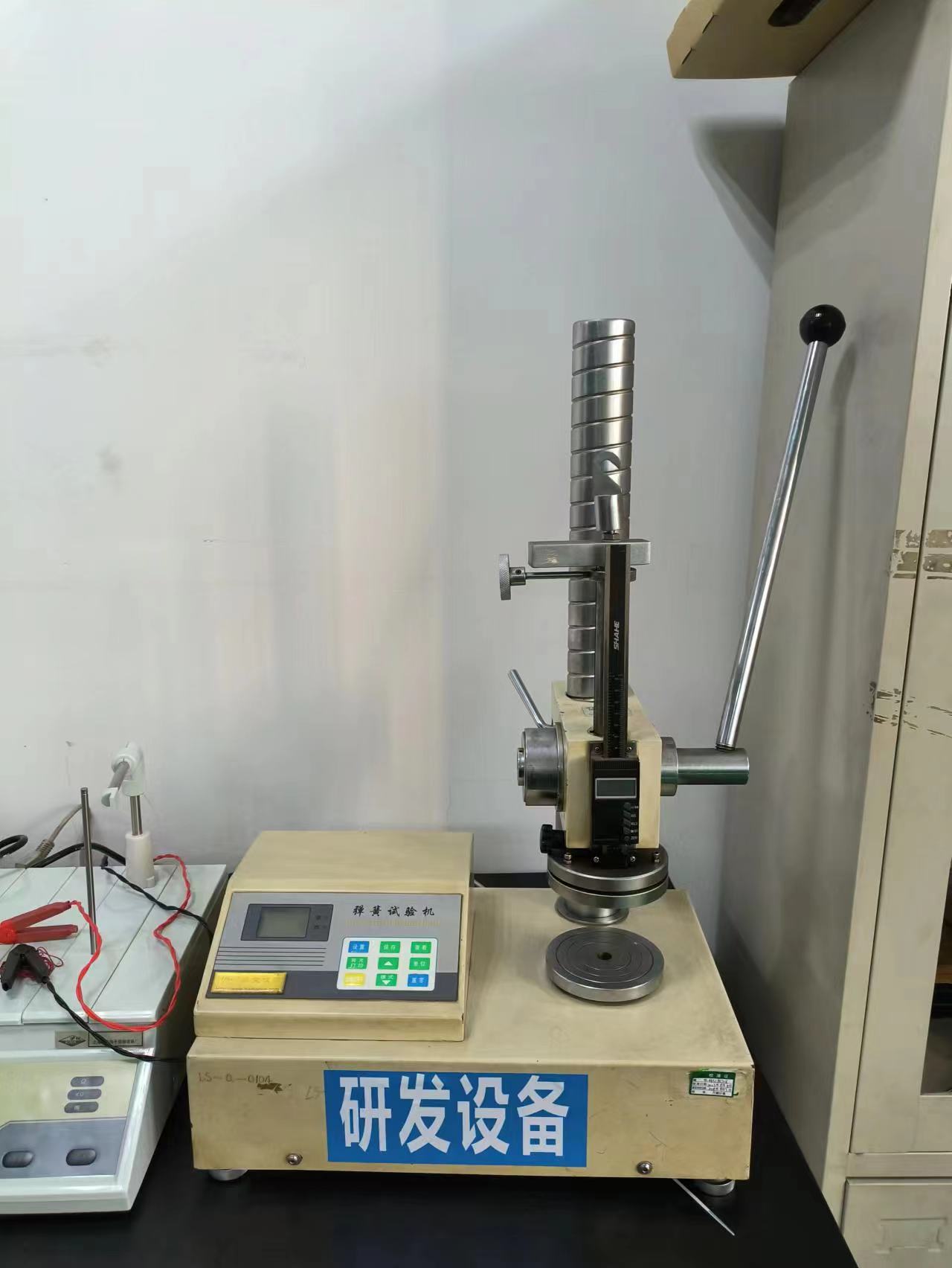
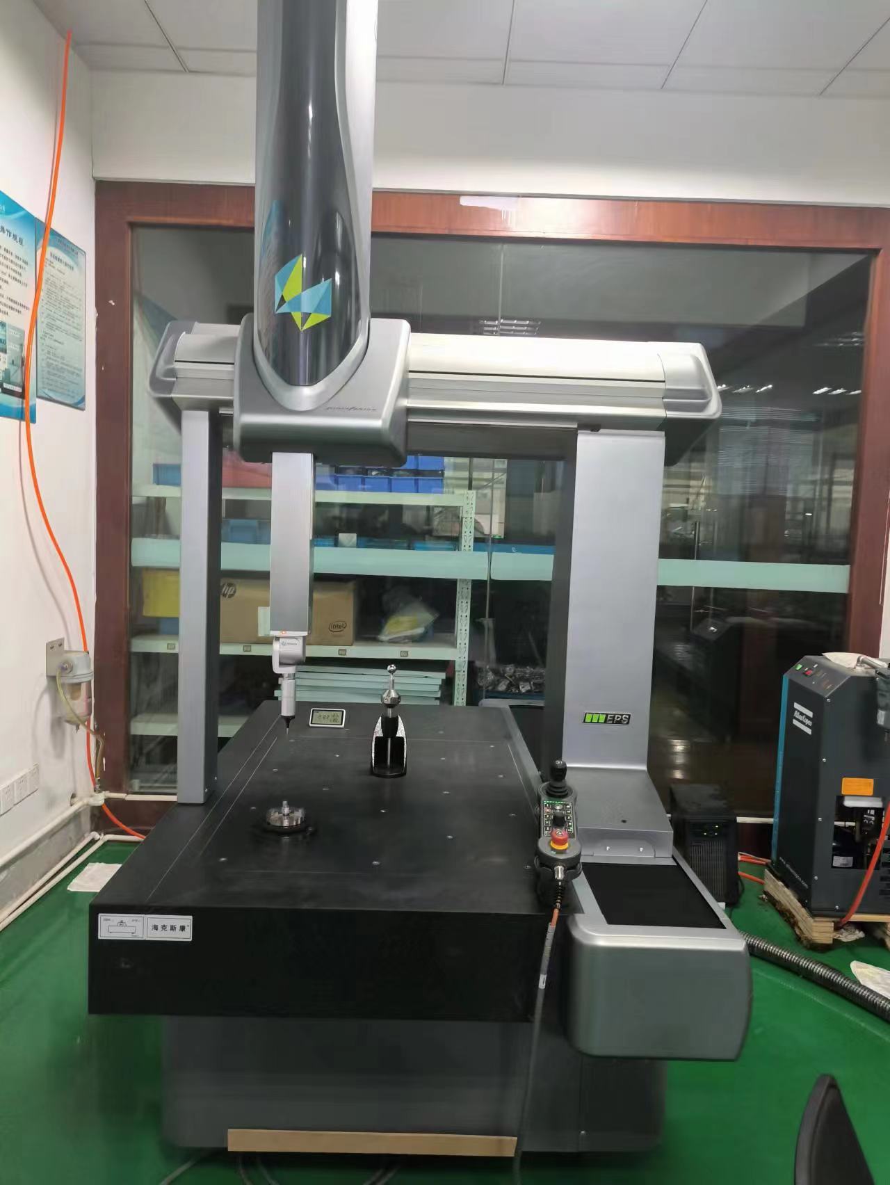
We have mature R&D equipment including design calculations, host system simulation, hydraulic system simulation, on-site debugging, product testing center, and structural finite element analysis.